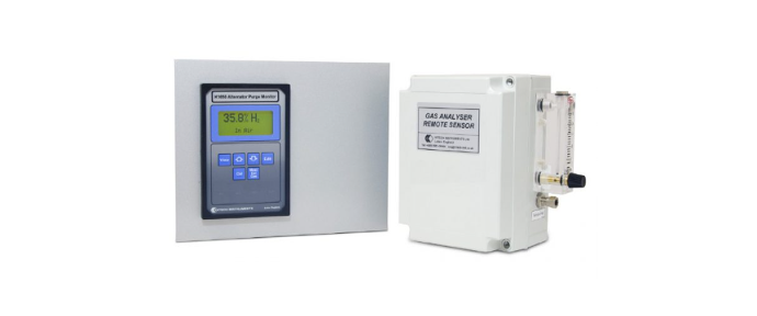
MTL K1650 – Hydrogen Purity And Purge Gas Analyser
· Single remote sensor
· Measures all gas purge stages
· ATEX certified for hazardous areas
· Simple, low cost servicing
· Optional sample systems
· Easy replacement of old analysers
Datasheet:Request for quote
Description
The K1650 fixed analyser consists of display /controller unit, pre-mounted in a panel for easy retrofitting and a remote sensor assembly. The remote sensor assembly consists of a katharometer supplied in a wall mounting, IP65 enclosure complete with flowmeter and sample flow control valve. The sensor is certified to European standards for use in Group IIB + H2 gases, and the zener barrier interface, incorporated in the display/controller unit, allows ‘live-working’ on the sensor unit.
Specifications
Display
Dot matrix LCD registering 4 lines of
alphanumeric characters
Ranges
0 to 100% CO2 in Air (Resolution 0.5%)
0 to 100% H2 in CO2 (Resolution 0.1%)
90 to 100% H2 in Air (Resolution 0.1%)
Stability
Better than 1% fsd/month
Accuracy
±1% fsd typically
Sampleflow
Between 100 to 300 ml/min for optimum
performance
Sample temp.
–10°C to +55°C (non-condensing)
Sample pressure
Set by vent pressure which must be
nominally atmospheric
Speed of response
T90 – typically 5secs or less
Sample connections:
Captive seal compression fittings
suitable for 0.25inch (or 6mm) outside
diameter tube.
Output (signal)
4 to 20mA, proportional to the selected
range. Maximum load 600Ω.
Alarms
Four user configurable alarms
programmable for level, function and
hysteresis are provided as follows:
• 1 alarm for CO2 in Air
• 1 alarm for CO2 in H2
• 2 alarms for H2 purity
Outputs are volt-free changeover relay
contacts rated at: 48V AC or DC, 0.5A
Ambient temp
–5°C to +40°C
Power supply
110/120V or 220/240VAC, 50/60Hz
power consumption, 12VA
Mounting
Electronics unit/Control/Display unit:
panel mounting with six screws
Remote sensor unit: wall/bulkhead
Options
• EEx d enclosure for K1650 electronics unit
• Larger electronics mounting plate,
dimensions: 432mm(h) x 381mm(w)
• Sample conditioning panel – see diagram


